- Intuitive icons for all power system elements.
- Multi-layer supports to easily view, select, edit, and present simulation results.
- Customizable bus base voltage levels and colour coding for system elements.
- Dedicated property window for each power system element.
- Edit the network and database either together or separately.
- ON/OFF switching control for all power system elements.
- Export single-line diagrams (SLDs) to formats like AutoCAD, PDF, BMP, GIF, JPEG, PNG, and TIFF.
- Compliant with widely accepted IEEE/ANSI standards.
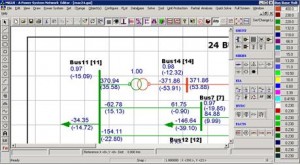
- View, print, or plot full or partial single-line diagrams (SLDs) showing only system topology, or with load flow results, fault study results, and other analysis outputs.
- Advanced tools like layering, panning, zooming, and scaling to any paper size (A5 to A0). Options to print full diagram, selected area, or current view; supports copy and paste.
- GPS interface integration.
- Protection simulation: trace relay operations forward or backward; first operating relay blinks for clarity.
- Dynamic simulation for “what-if” analysis without changing the central database.
- Generate multiple PDFs by selecting Numerous GUI files linked to the same database.
- Batch execution support for Load Flow Analysis (LFA), Transient Stability (TRS), and System Protection.
- Optimal capacitor placement functionality.
- Switching optimization feature to improve system performance.