Power system protection study deals with precautionary measures to be taken to safeguard the power system during abnormal operating conditions which involves periodic fault studies followed by relay setting, checking and coordination studies. Power System Protection can be current graded or time graded or a combination of both. The equipments in a power system need to be protected against faults which are external or internal faults. The schemes are broadly classified as unit protection schemes and graded (Time/Current) protection schemes.
Over current relay coordination studies provide Plug and time settings for appropriate functioning of protective relays with proper discrimination. This assures required reliability, sensitivity and selectivity of power system equipment.
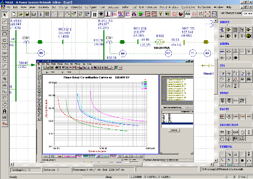
The over current relay coordination study gives :
- Plug Settings – for the phase/ earth relays
- Time dial settings – for the phase/ earth relays
- Instantaneous setting – for the phase/ earth relays
- Primary and Backup Pairs
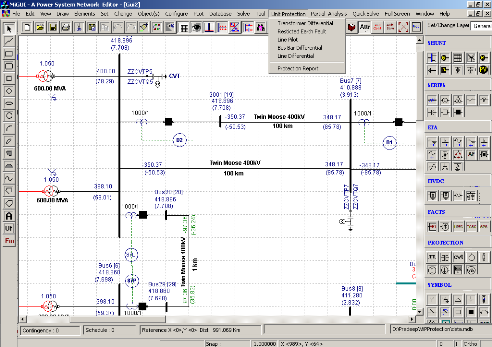
The output of the module provides the coordinated settings of the relays. These can be viewed in the form of graphs and reports. User defined settings also can be verified for the system. The co-ordination curves can be viewed and checked for the proper coordination.
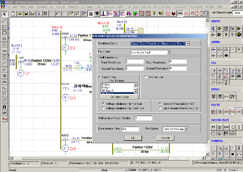
The distance protection is the most widely spread protection in transmission and sub-transmission networks. Distance relay responds to the ratio of measured voltage and current and operates if measured impedance (V/I) is less than the threshold value. Typically, distance relays are provided with multiple zones of protection to meet the stringent selectivity and sensitivity norms.
The key features of the distance relay coordination algorithm are :
- Phase loop and earth loop impedance settings as per relay make and model
- Load encroachment settings
- Power Swing Blocking settings
- Arc and Tower footing resistance
- Impedance seen by relays for given fault location and type
The simulation output is also used for validation of user-defined settings.
Unit protection schemes are used for protecting components like transmissions, transformers, bus bars, generators etc or a zone/sub-system. It does not involve time grading and relatively faster in operation. Unit protection is usually achieved by means of comparison of quantities at the boundaries of the zone.
Unit protection algorithms provide the settings for the relays used in :
- Transformer Differential Protection scheme
- Line Differential Protection scheme
- Bus bar Differential Protection scheme
- Partial Bus bar Differential Protection scheme
- Generator Protection scheme
- Restricted Earth Fault
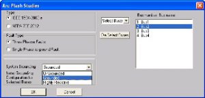
Safety being the key concern, Arc Flash Analysis provides limiting values of arcing current and incident energy to define the safe boundaries for the working personnel in the electrical installations.
The analysis determines the following :
- Arcing current
- Incident energy
- Hazard Risk Category (HRC)
- Personal Protective Equipment (PPE) requirements in an electrical system
The following standards are referred to compute safety requirements :
- IEEE 1584-2002a
- NFPA 70E 2012
The output of the Arc Flash Analysis provides the safety label which showcases the necessary information/ warning details for the safe working distance and the PPEs to be used.